An Easy DIY PSU for the Lab
This project is a quick win to solve all (well, maybe not all but close) your needs of power source in your lab. By reacconditioning an old computer PSU you can have a nice variety of power options for your projects.
So, after I built the table computer (yeah, some day should write about that one: a computer inside the tabletop) I had a spare ATX PSU around and thought about repurposing it. It’s always handy to have a PSU with several outputs in your lab, and the most common are already present in a computer PSU.
After checking online some projects done by other people I decided to go and design my own because in most of those the PSU was modified to serve this new role. Computer PSU often have a lot of cables for all the things you need to power inside of the computer and the first thing most of those projects where doing is to cut out the extra cables. I didn’t want to mutilate my PSU, I may need it in the future to power a computer.
The other reason is that I wanted a modular design. Today I have 4 outputs: 3.3, two of 5 and 12 volts. Tomorrow I may switch one of the 5 volts sections to have 3 or 4 USB outputs (nowadays almost every electronic devices is powered by a USB connector). Or maybe switch two sections and add one with variable power output.
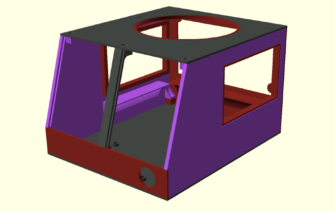
The design is pretty simple: just a few walls to confine all the components and some screw holes keep everything together. The computer PSU is upside down, so the air intake can be on top. It’s elevated by slopes in three of the four sides to make room for the unused cables bellow. As I didn’t want to remove the cables I had to place them somewhere: the top has a hole for the fan abd cannot be covered, same as the rear (but for exhaust), the front is where the outputs are going (and I didn’t like it to be too long) and if I put them in a side them the design wouldn’t be symetrical (or would be too big if making an empty pocket in the other side). So the best solution was to put them underneath the PSU.
Then, I jsut opened a couple of windows in the sides to make it look cooler. As the PSU is black and red, I used those colors for the 3D printed parts, providing a more consolidated look and feel.
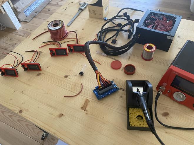
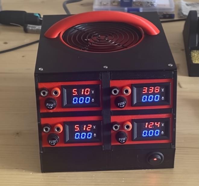
After designing and 3-D printing the case, building this is quite strait forward. I used standard components from Amazon: all the interchangeable sections have a voltimeter/amperimeter, a replaceable fuse and two banana connectors, they are connected to PCB with the ATX connector for the PSU and many cable sockets for all the outputs that the PSU offers (also from Amazon).
The final outcome is a compact PSU, with several outputs that can be easily carried by its handy handle. Specially useful are the voltimeter/amperimeter modules that provide a quick view of the consumption of your circuit (and the voltimeter part helps on providing the correct voltage to your circuit). I’ve already started using it in my prototypes, before moving them to a more permanent power source.
Let me know your thoughts.
Back in a bit!