Improving the Giant Clock
Second part on the giant clock series. The first part is a brief description with the basic code to make it work, in this one we are going to improve our clock with automatic brightness based on the ambient light on the room.
But first, a screenshot of how it looks on Home Assistant (I missed that in the previous post):
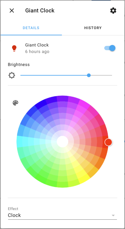
It’s just a basic RGB light that you can turn on or off, set the brightness or change color. It has two basic effects: the clock itself and a countdown of 30 sec.
So, if we want to change the brightness based on the amount of ambient light, first we need to know how much light there is in this room. If you have other device in Home Assistant that provides this information, you could control the brightness from HA, but is not my case and I wanted it to be autonomous.
Let’s add a photoresistor to the clock. Just create a voltage divider with another 10k resistor (for example) and connect it to a ADC pin on your board. Sparkfun has a nice article about photoresistors.

Don’t forget to make a hole for the photoresistor to see outside!
Now, we need to modify giant-clock.yaml file to include the new sensor (remember this file uses esphome to build the firmware, if you don’t know what something does check their website):
sensor:
  - platform: adc
    pin: GPIO35
    name: "Living Room Brightness"
    update_interval: 10s
    attenuation: "11db"
    unit_of_measurement: "%"
    accuracy_decimals: 0
    filters:
      - multiply: -25.64
      - offset: 99.996
      - median:
          window_size: 5
          send_every: 3
          send_first_at: 3
      - or:
        - throttle: 300s
        - delta: 5
    on_value:
      then:
        - light.control:
            id: all_leds
            brightness: !lambda |-
              double y=135.0-65.0/(1.25*log10((x+50.0)/17.0));
              return max(min(y*0.01, 0.75), 0.14);
The first lines are quite straightforward: select a pin that has ADC capabilities, choose a name and the attenuation at “11db” provides the maximum range of values (0-3.9V). Then, the filters will allow me to transform that value into something more meaningful.
The reading from the ADC pin is close to 0V when is very bright in the room and 3.9V when the room is dark. by multiplying and adding that offset I get a value 0-100 with 0 being dark and 100 being the brightest the sensor can handle. I added this to HA to see how bright it gets during the day:

It increases during the day, as expected, reaching about 80%. It can go up to 95% if I open the windows (they have a coating to reduce UV light, that also blocks some visible light). At night it’s about 10% when I have a small light on (like when watching TV) and it goes close to 80% when the main lights are on.
When this value changes, it updates the brightness of the LEDs (the main light component). At the beginning, I was trying a direct conversion: to use this value as the new brightness of the LEDs, but when the LEDs are below 10% they turn off directly. So, I decide to go for a logarithmic function:

It starts at 24% and increases quickly at the beginning and then it stabilizes with a maximum of about 80%. I could remove the last checks to have the output value on the boundaries 14-75% but it doesn’t hurt and I’m too lazy for such small change.
This closes the giant clock series. I’m still looking for a new project, what should I build?
Back in a bit!